 Made in China
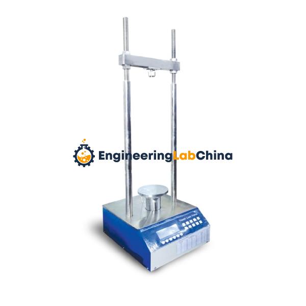
Loading Frame
Load frame is steel welded structure with high stiffness where top and bottom plates are tied with side place.
It is designed to withstand a few million times of full cycles of loading without any sign of distortion or fatigue. These frames are light in weight.
The top plate has the upper spherical seated platen with oil filled ball seat assembly as per IS : 14858-2000 to take care of any irregularity of the specimen surface or slight misplacement of the specimen from the central position. The upper and Lower loading platens are hardened and has hardness The flatness tolerance is 0.03 mm and the roughness value (Ra) in the range of 0.4ìm.
The base carries a fine finished servo controlled hydraulic cylinder with hardened and finest abraded piston.The bearing surface of the Lower Loading platen has marking inscribed to facilitate proper centering of cubical and cylindrical specimen of different sizes.
The frame is provided with safety guard doors and transparent fragment guards (both front and rear) as a protection to the operator while at the same time giving an unobstructive view of the specimen under test. Proximity switch/ Limit switch is provided as a safe guard against over travel.
A load cell or pressure transducer is fitted in the frame with testing range from 1% to 100% capacity of machine with an accuracy of ± 0.5% of indicated load. A displacement transducer is fitted with the ram to measure the deformation of the specimen.
HYDRAULIC POWER PACK
Hydraulic power supplies are compact in design and are suitable for the supply of required flow and pressure for the movement of the actuator. It has an oil tank of adequate capacity, vane type pump powered by a three phase motor. All the electrical controls including the temperature controller are fixed on one side of the tank. It includes all the accessories like pressure line filter, return line filter, oil level, relief valve, pressure gauge, digital temperature indicator and air cooled heat exchanger. Anti vibration mountings are provided as standard along with the HPS.
Technical specifications:
Flow of the pump : 2 & 4 LPM
Motor capacity : 3 H.P.
Capacity of the tank : 40 Litres
Max. Operating pressure : 210 – 600 Bars
System will be supplied with necessary cable and fittings
for the operation of the machine. Total machine operates on 440VAC 3 phase supply.
Note: Hydraulic Power pack can be supplied with manifold block with solenoid valves to operate multiple loading frames (Max. up to four can be operated through same hydraulic power pack
C) PC BASED CONTROL SYSTEM AND CONTROL SOFTWARE
Control system provides the digital servo control, Ramp generation & low frequency wave generation for the machine actuator, data acquisition, etc. for the continuous operation of the system.
(a) Signal Conditioning & Controlling Unit
controller basically consists of signal conditioning unit and controlling unit. Signal conditioning unit receives the output signal from the various transducers (Load cell/Pressure Transducers, LVDT, Strain gauge etc.) and amplifies and process that signal as per the requirement and transfer it to computer through connecting cables where it is accepted by the data acquisition system. The output from the signal conditioning unit for each transducers ranges from 0-5V.
Control is on Load/ Stress or Displacement or Strain basis. It consists of dedicated servo-controller card that gives the desired processed signal through the P.I.D controller to the servo valve to operate in selected control mode. It also sends the signal to computer and accepts the command from the software to operate in desired manner. The parameters like rate of loading, safety limits for load can initially be programmed through the software. The facility is given to program the rate of loading from 0.1kN/sec-50kN/sec in Load control and 0.01mm/sec-1mm/sec in displacement control.
Specifications of Controller
Auto PID operation with Closed loop update rate of 10 kHz to control Pace rate automatically as programmed in the software
No. of control channels: 4 (Load/Displacement/ Strain/ External LVDT Control)
Selection and controlling of multiple frames (Up to 4)
Type of Loading: Static and low frequency cyclic
High speed Data Acquisition card with 100 kHz sampling rate
Computerised control operation to Start, Stop & Hold the test system
Resolution: Load : 0.1kN up to 1000kN & 1kN above 1000kN
System accuracy
Load accuracy : < ± 0.5% of indicated value |
Displacement accuracy: <± 0.5% of indicated value
Displacement Measurement: Through LVDT
Displacement Range: 50mm
Displacement Resolution: 0.001mm
Rate of Loading:
Load control: 0.1kN/sec. to 50 kN/Sec
Displacement control: 0.01mm/ sec to 1mm/sec
Rate of increase of net deflection: 0.00016mm/sec – 0.001mm/sec.
8 Additional input channels for external transducers such as load cell, pressure transducer, LVDT etc.
Supply Input- 220-240 VAC, 50 Hz
Computer for Controlling and Data acquisition
System is provided with dedicated computer of following or better configuration at the time of supply with built in data acquisition card.
Computer
Intel i5 processor, 320 GB HDD, 4GB RAM, DVD R/W drive, Key Board, Optical Mouse, 6USB Ports, 19” LCD Monitor, Deskjet Colored Printer, UPS
Application Software
Application software is the integral part of the system for precise operation, Data Acquisition, storage, processing, analysis and reporting. The software package includes test routines for Compression and Flexure tests on concrete according to relevant standards such as IS, EN, ASTM etc.
Test Software- Salient Features
Windows based user friendly software with easy graphical user interface
Programmable rate of loading/displacement in load and displacement control i.e. kN/sec. or N/mm2/sec or mm/sec or micro strain/sec. and sample parameters (Shape, Dimension, weight etc.)
Facility to set up and execution of monotonic, cyclic and user defined test procedures
Facility to create Test Profiles for different samples
Provides block programming with sine, square, triangle, ramp, hold, processes, and ability to play digitized profiles
Facility to change the rate of loading or rate of displacement during the test
Auto Fast lift operation to adjust the gap
Autozeroing/ Independent Taring of each channel
Auto release of machine after sample failure
To see the post failure behavior of the specimen
Computer/Software programmable Safety Limits for Load and Displacement
Facility to hold load at desired point and restart the loading during the test.
Online display of numerical values of Load, Stress and Displacement simultaneously with peak hold facility
Online plotting of data of Load v/s Time, Displacement v/s time, Load v/s Displacement, Stress v/s Strain graphs
Real time clock for tracking date, time and runs
Facility to save test data along with order information about the specimen such as age, specimen no., size, dimensions etc. in user defined file/directory
Facility to avoid unauthorized use by creating users password
Analysis Software
Plotting of following graphs-
Load v/s Time
Displacement v/s Time
Load v/s Displacement
Stress v/s Strain
Stress v/s Time
Calculation of various results (Young’s modulus, Maximum strain, Compressive Strength, Flexural Strength, Flexural toughness etc.)
Facility to plot the data for a selected run
Comparative analysis using multi graphs
Statistical analysis of the test results
Batch Summary Report Generation
Detailed Summary Report Generation
Facility to print Test Reports
Facility to Export Data to MS Excel
SAFETY FEATURES
The following safety features are incorporated in the system-
Over Load protection
Over Travel protection
Front door for operator safety
Low oil level Indicator
Protection against contamination of oil
As leading loading frame manufacturers, suppliers & exporters in China, Engineering Lab China combines factory-direct pricing, strict quality control and reliable worldwide shipping. Every Loading Frame is built in-house in Guangzhou City to deliver dependable performance for engineering training and teaching environments.
We manufacture every Loading Frame at our own facility in Guangzhou, China. No middlemen — you get factory pricing on Engineering Laboratory Trainer Kits, Training Charts and Educational Equipment.
Every Loading Frame passes a strict outward quality check before dispatch, so it stands up to daily use in Industrial Training Institutions, Engineering Colleges & Polytechnics.
From a single trainer kit to a full lab tender, our team manages packaging and prompt international delivery so your Loading Frame arrives on schedule, anywhere in the world.
EngineeringLabChina is a leading loading frame manufacturers, loading frame suppliers & exporters in China. Whether you need a single unit for a lab refresh or a complete tender for a polytechnic, we handle Engineering, Procurement, Installation and Commissioning under one roof.
We accept Wire or Telegraphic Transfer / Letter of Credit. Shipping is based on consignment size — contact us with your requirement for an accurate quote.
Share quantity, destination country and any custom specs for the Loading Frame.
Our team replies with factory pricing, lead time and shipping options within 24 hours.
We manufacture in Guangzhou, run a quality check and prepare export-ready packaging.
Consignment dispatched by your preferred mode — sea, air or courier — to your door.
Full product category index — manufactured in Guangzhou, exported worldwide.